Hospital Design is a collaboration between architects, engineers, medical planners and most importantly the clients. Therefore, it is essential that all parties work together in order to express the exact client vision.
Facility planning
Overview

Process & Methodology
An analysis of the functional requirements of the Project, resulting in a detailed list of functional space allocations.

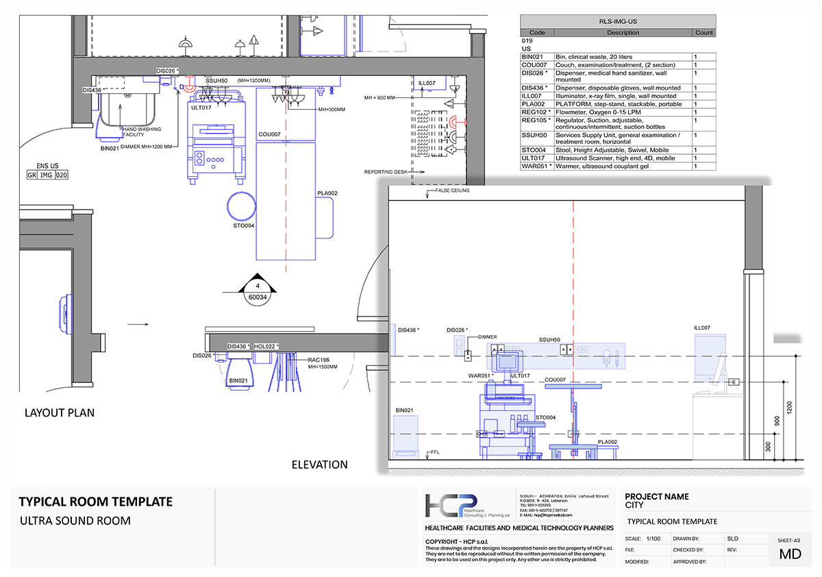
Graphical illustration of general layout of individual medical and paramedical spaces within the facility. The indicative graphical illustration helps the design team to understand the physical form and functional characters of medical and paramedical spaces within the building envelope. These drawings show examples of the typical layout and furnishing of the space, clearances and minimum floor areas as required by the international guidelines.

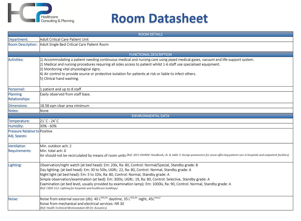
Detailed attributes used for the gross calculation of building engineering elements. The room data sheets aimed at providing the Engineers with nominal data pertaining to each medical and paramedical space in the facility.

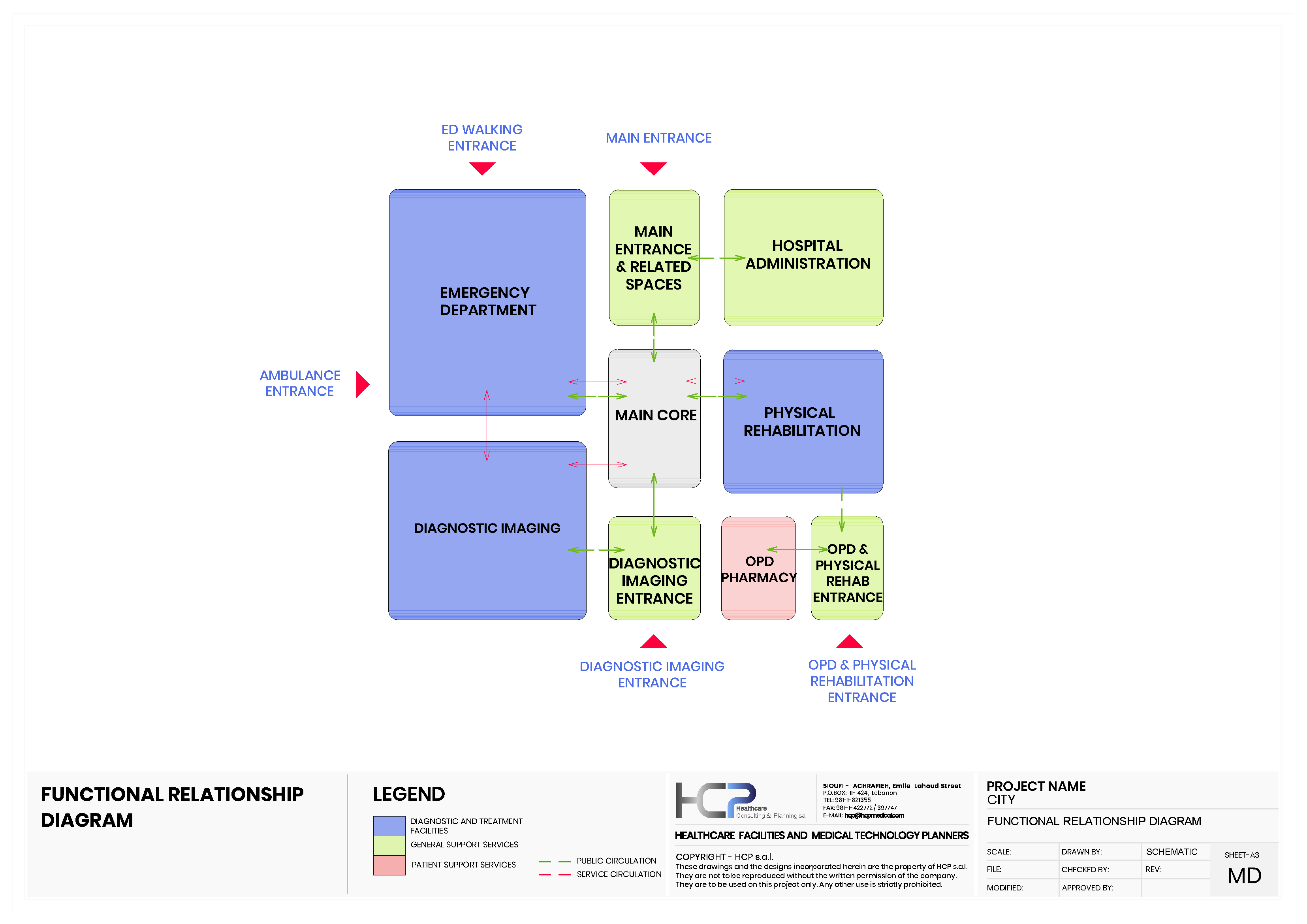
shows the functional dependencies and relationships between the different spaces, services, materials & people.

To allocate the various departmental within the envelope of the building. Run in collaboration between the Architect and the Medical Planner.

The stacking diagram is a multi-dimensional, color-coded, graphic representation of all departments, arranged in layers floor-by-floor.

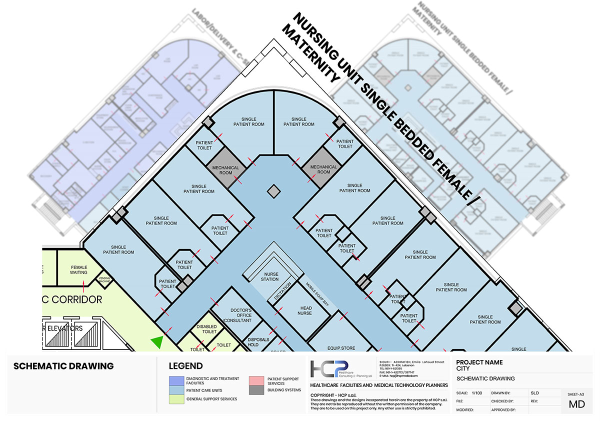
The schematic drawings shows the details of the internal organization of spaces down to room-level. These drawings are subject for modification by the Architect and the medical planner to ensure compliance with design attributes of the facility.

The circulation diagrams show the circulation pathways interconnecting the various departments. The aim is to have separate circulation routes for patients, staff, visitors and materials, thus ensuring patient privacy and dignity, allowing staff to move easily and deliver patient centered services, reducing risk of cross-infection; and protecting patients from disturbance and cross-infection risk.


 Get in touch with us today!